- 您现在的位置:买卖IC网 > Sheet目录975 > DLP-TILT-G (DLP Design Inc)BOARD EVAL ACCEL/TILT/VIB SENSOR
�� �
�
�2.0� ELECTRICAL� INTERFACE� DESCRIPTION�
�Refer� to� the� electrical� schematic� at� the� end� of� this� document� for� additional� details.�
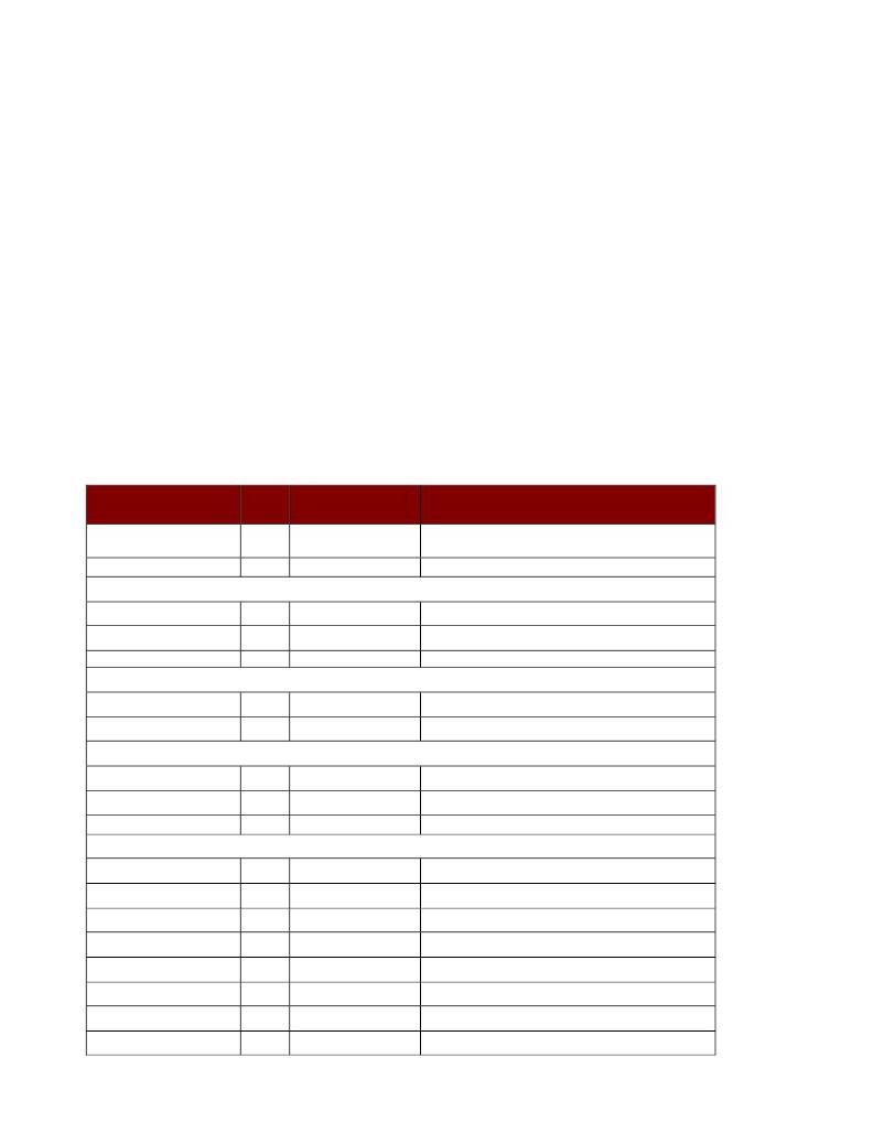
�Pin�
�1�
�2�
�3�
�4�
�5�
�6�
�7�
�8�
�9�
�10�
�11�
�12�
�13�
�14�
�Description�
�MCLR�
�Vin1�
�B6/PGC�
�Vin2�
�SWVCC�
�B0�
�Ground�
�Ground�
�B7�
�B1�
�B3�
�B4�
�Ground�
�Ground�
�Comments�
�Pulling� this� pin� to� ground� will� reset� the� microcontroller.�
�See� Note1.�
�Analog� input� for� voltages� in� the� range� of� ±3V.�
�Analog� in� (0-3V)� or� digital� I/O.� See� Note1,� Note2.�
�Analog� input� for� voltages� in� the� range� of� ±3V.�
�3� Volt� output;� switched� on� once� host� enumeration� is�
�complete.� See� Note1.�
�Digital� I/O;� See� Note2.�
�Note1.�
�Analog� in� (0-3V)� or� digital� I/O.� See� Note1,� Note2� .�
�Digital� I/O.� See� Note2.�
�Digital� I/O.� If� held� low� at� power� up,� Pointing� Device�
�functionality� is� activated.� See� Note2.�
�Digital� I/O.� See� Note2.�
�Note1� :� These� pins� are� used� for� reprogramming� the� Flash� program� memory� area� (a� user-supplied� device�
�programmer� is� required).�
�Note2� :� Weak� pull-ups� in� the� microcontroller� are� enabled� for� Port� B� by� default.�
�2.1� SOFTWARE� INTERFACE� DESCRIPTION�
�Royalty-free� Virtual� COM� Port� drivers� are� available� for� immediate� download� from� www.dlpdesign.com� .� The�
�VCP� drivers� are� available� for� the� following� systems:�
�?� Windows� 2000� /� XP� /� VISTA�
�?� Windows� CE�
�?� MAC� OS-8� and� OS-9� (Mouser� function� not� supported)�
�?� MAC� OS-X� (Mouser� function� not� supported)�
�?� Linux� 2.40� and� greater�
�The� DLP-TILT� supports� two� standard� baud� rates:� 38,400� (power-up� default)� and� 128,000� baud.�
�Communication� with� the� DLP-TILT� is� accomplished� by� simply� opening� the� COM� Port� at� 38,400� baud� and�
�sending� single-byte� commands.� The� commands� are� outlined� in� Section� 3.0.�
�2.2� QUICK� START� GUIDE� FOR� WINDOWS�
�A.�
�B.�
�C.�
�Download� the� modified� Virtual� COM� Port� (VCP)� drivers� from� www.dlpdesign.com.� Unzip� these� files� into� a�
�new� folder.� The� VCP� drivers� that� are� part� of� the� Windows� XP� operating� system� will� not� work� as� the� PID�
�code� has� been� changed� to� FBFA.�
�Connect� the� DLP-TILT� module� to� the� host� PC,� then� load� the� USB� drivers� obtained� in� Step� A.�
�Open� Device� Manager� and� look� in� “Ports� (COM� &� LPT)”� to� determine� the� COM� port� number� that� Windows�
�has� assigned� to� the� DLP-TILT� module.�
�Rev.� 1.1� (May� 2009)�
�3�
�?� DLP� Design,� Inc.�
�发布紧急采购,3分钟左右您将得到回复。
相关PDF资料
DM160211
KIT DEV MTOUCH PROJ CAPACITIVE
DM163026
BOARD DEMO LOW POWER SOLUTIONS
DM164125
BOARD DEMO PICDEM TOUCH SENSE 1
DM164128
KIT DEV PICDEM TOUCH SENSE 2
DM183026-2
KIT EVAL MTOUCH CAPACTIVE
DM183026
KIT EVALUATION PIC16F/PIC24F
DNGL
GROUND LUGS 1 1/8X1 3/16"
DO KA TYPE 21-5M
FM3 CABLE W/CONN 5M
相关代理商/技术参数
DLP-TTL232R-3V3B
功能描述:电缆组件 From FTDI USB-Seril CABL I/O3.3 2MM PIN RoHS:否 制造商:Molex 产品:Power Assemblies 类型:Cable Assembly 连接器端口 A:No Connector 连接器端口 A 管脚计数:4 连接器端口 B:No Connector 连接器端口 B 管脚计数: 型式:Male 线规 - 美国线规(AWG):20, 28 长度:0.305 m 颜色:Black, Red
DLP-TXRX
功能描述:界面模块 USB to Serial Adapter for MCUs
RoHS:否 制造商:4D Systems 产品:Serial Converters 通道/端口数量: 数据速率: 接口类型:USB, UART 工作电源电压:3.3 V, 5 V 最大工作温度:
DLP-TXRX-G
功能描述:界面模块 USB to Serial Adapter for MCUs
RoHS:否 制造商:4D Systems 产品:Serial Converters 通道/端口数量: 数据速率: 接口类型:USB, UART 工作电源电压:3.3 V, 5 V 最大工作温度:
DLP-UC232R-10
功能描述:电缆组件 From FTDI UC232R "CH iPi 10cm USB-SER CBL RoHS:否 制造商:Molex 产品:Power Assemblies 类型:Cable Assembly 连接器端口 A:No Connector 连接器端口 A 管脚计数:4 连接器端口 B:No Connector 连接器端口 B 管脚计数: 型式:Male 线规 - 美国线规(AWG):20, 28 长度:0.305 m 颜色:Black, Red
DLP-UCF2321
功能描述:开发板和工具包 - PIC / DSPIC FLASH2 TARGET BOARD 18F2321 w/IDE 2k Ltd RoHS:否 制造商:Microchip Technology 产品:Starter Kits 工具用于评估:chipKIT 核心:Uno32 接口类型: 工作电源电压:
DLP-UCF4420
功能描述:开发板和工具包 - PIC / DSPIC FLASH2 TARGET BOARD 18F4420 w/IDE 2k Ltd RoHS:否 制造商:Microchip Technology 产品:Starter Kits 工具用于评估:chipKIT 核心:Uno32 接口类型: 工作电源电压:
DLP-UCF917
功能描述:开发板和工具包 - PIC / DSPIC FLASH2 TARGET BOARD 16F917 w/IDE 2k Ltd RoHS:否 制造商:Microchip Technology 产品:Starter Kits 工具用于评估:chipKIT 核心:Uno32 接口类型: 工作电源电压:
DLP-USB1
功能描述:界面模块 Legacy USB Adapter
RoHS:否 制造商:4D Systems 产品:Serial Converters 通道/端口数量: 数据速率: 接口类型:USB, UART 工作电源电压:3.3 V, 5 V 最大工作温度: